 |
The exhaust
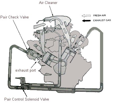
emission control system consists of a secondary air
supply system which introduces filtered air into the
exhaust gases in the exhaust port. Fresh air is drawn
into the exhaust port whenever there is a negative
pressure pulse in the exhaust system. This charge of
fresh air promotes burning of the unburned exhaust gases
and changes a considerable amount of hydrocarbons and
carbon monoxide into relatively harmless carbon dioxide
and water vapor. The PAIR system is controlled by the ECM
using check valves and a solenoid. Removal of the PAIR system will yield three main benefits: 1) weight reduction 2) reduction of engine compartment clutter 3) increase in the scavenging ability of the exhaust system with the added benefit of alleviating the popping on deceleration that so many RC51 owners complain of after installing an aftermarket exhaust PAIR System Diagram (Figure 1) |
|
|
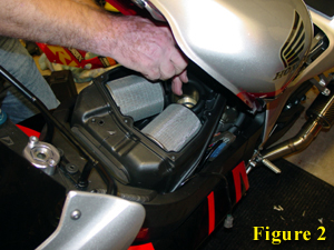
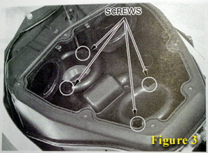
Begin by lifting the tank and removing the cover from the airbox. Next remove the rear velocity stack. Once the velocity stack is out we can remove the air filters, starting with the left (air filters may be modified at this time--see "Air Filter Modification Guide" in the mod section.) (Figure 2) With the air filters out of the airbox, unscrew the front velocity stack (note: the rubber plug on top of the airbox must be removed to access the forward screw on the front stack.) The front stack will remain in the airbox (Figure 3.) The airbox is now free of the throttle bodies and can be lifted slightly to expose the three hoses attached to the bottom. Disconnect all three hoses (one on the right, two on the left) and remove the airbox. | |
|
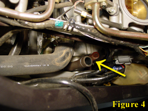
The larger black hose in Figure 4 is the filtered air supply hose for the PAIR system and the pink hose is the airbox drain tube. OPTIONAL: The pink hose can be removed from the left side of the bike. The other hose will be removed later. | |
|
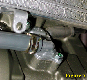
It is now time to
remove the front and rear PAIR Check Valve Covers.
(Figure 5) Rear cover not pictured. Front Cover: Requires removal of the lower inner fairing. Rear Cover: Requires the tank to be propped as high as possible. |
|
|
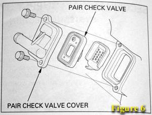
OPTIONAL: The PAIR Check Valve and the Flame Arrestor can be removed (Figure 6), although this will remove the seal between the PAIR Check Valve Cover and the engine. When this is done an alternate sealing method must be used (i.e. liquid gasket) when reinstalling the PAIR Check Valve Cover. | |
|
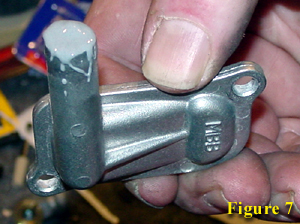
In order to plug
the hole in the PAIR Check Valve Cover, we need to
use an appropriate metal bonding epoxy (JB Weld works
wonders) (Figure 7). The JB Weld will need something
to rest against when it is gooped into the hole. We
stuffed a wad of paper down the hole leaving about a
half-inch of space for the JB Weld to set in. The
paper will remain in the PAIR Check Valve Cover.
Both covers need to be plugged in the same fashion. The
PAIR Check Valve Covers can be reinstalled after the
JB Weld has cured for approximately 4 hours, however, the
engine should not be started until the JB Weld is fully
cured. ** This step can be avoided by purchasing Block-off plates from Dan Kyle. |
|
|
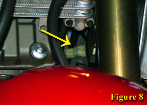
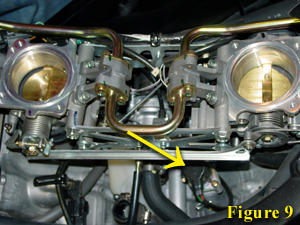
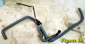
While the covers are curing, we will remove the PAIR Control Solenoid Valve and attached hoses. First, disconnect the solenoid plug located at the front of the bike under the oil cooler (Figure 8). You will have to peel back the black weatherproof boot to expose the connector. The solenoid (Figure 9) is now free and can be removed (it is mounted on a metal rod via a rubber grommet) along with the attached hoses (Figure 10.) | |
|
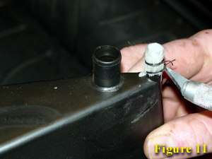
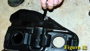
Now we just need
to seal the remaining holes in the airbox. This can be
accomplished in a variety of ways. Here we've used tennis
racket tape, which has been secured using string (Figure
11) and then sealed with liquid vinyl (Figure 12). Rubber
caps could also be used. In order to provide a drainage point for the airbox [needed if the pink drain tube was removed (Figure 4)] a small hole can be punctured through the center of the seal in the larger outlet "nipple" once the seal had dried. Once everything has cured, the bike is ready for re-assembly. |